
 Strale
- Posts : 26
Join date : 2018-10-09
 Need Support
Sun Mar 10, 2019 11:04 pm
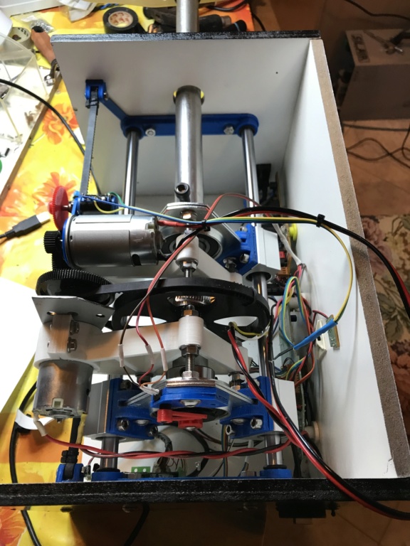
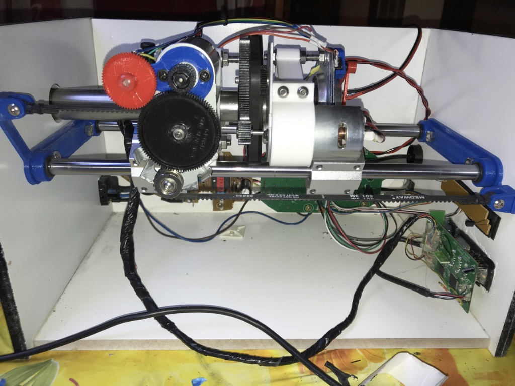
I finally finished my version of the FFB Yoke
and today i "fired" it for the first time.
here some pictures of the earlier stages

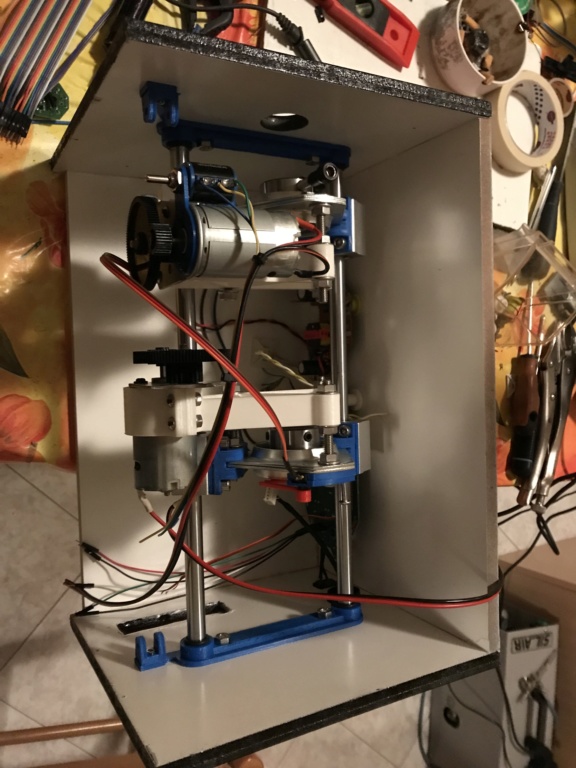
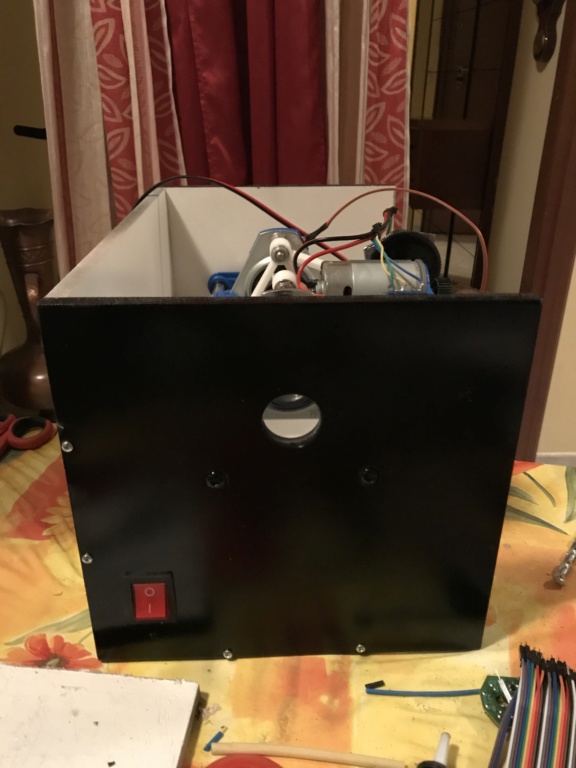
Saitek's Yoke implemented with its electronics
Sidewinder correcly found by windows, axis centered !


BUT when i apply the power ... nothing happens I tryed to cover the IR emitter or the Receiver but nothing happens
the only thing from original instruction that i missed is to add the on-off switch of the brown wire !
maybe it's this the issue ?
Seeking for help.
and today i "fired" it for the first time.
here some pictures of the earlier stages
Saitek's Yoke implemented with its electronics
Sidewinder correcly found by windows, axis centered !
BUT when i apply the power ... nothing happens I tryed to cover the IR emitter or the Receiver but nothing happens
the only thing from original instruction that i missed is to add the on-off switch of the brown wire !
maybe it's this the issue ?
Seeking for help.
 tomzah
- Posts : 18
Join date : 2018-12-05
Re: Need Support
Mon Mar 11, 2019 1:12 pm
do you have the original led board? It can be used for troubleshooting your problem.
If yes. Plug it in and does it light up and blink??
If yes. Plug it in and does it light up and blink??
- Strale
- Posts : 26
Join date : 2018-10-09
Re: Need Support
Mon Mar 11, 2019 2:20 pm
Yes,
Original led board is installed
when USB cable il plugged in it shows two blinking green leds
when applied power the two leds are on and steady
I also experienced a weird behavior ... in the calibration page even if no other pots than pitch and turn pots are connected
i see some flickering in the throttle axis ... When having a flight test on P3D V3 using keyboard for throttle (F3 / F4) if pitching
throttle was decreasing power)
nothing bad should have happened to the transformer board as it's connected to a lighting switch and when the power cable is installed
the switch is lighted up only when in "ON" position.
No bad "burnt" smell
No noise
No Heating on motors
How should i procede in a step to step way ?
Thanks
- tomzah
- Posts : 18
Join date : 2018-12-05
Re: Need Support
Mon Mar 11, 2019 3:49 pm
what version of windows are you running.
Next.. Go to Setting up usb controllers.
The Microsoft FFB2 should show up (the way your led light reacted is very good and indicates the microprocessor is alive on the FFB2 board.
Under properties you should be able to see the cursor move in the box when you pull on the yoke and roll the yoke.
You can also set the calibrations of the pots in the settings tab in the upper left.
you can also unplug the cable going to the IR board as it is not needed right now.
FIY it is the big one called P1 / handle..
- Strale
- Posts : 26
Join date : 2018-10-09
Re: Need Support
Mon Mar 11, 2019 4:24 pm
Tomzah
Windows is W10 X64 PRO
Everything in the control panels is working ! I see the Microsoft FFB2 device, i can check axis and calibrate (as i did !)
Everything seems OK (not considering at this stage the flickering of the throttle axix - that should stay steday as no pots are connected to the Rudder / Throttle)
the problem are the MOTORS that don't move
Will check this evening removing the IR Pcb unisntalling the big connector
meanwhile if you want to procede in the step by step guide ... i'll do the steps when @ home.
- tomzah
- Posts : 18
Join date : 2018-12-05
Re: Need Support
Mon Mar 11, 2019 4:43 pm
Thanks for the information.
I may ask redundant questions to make sure we are on the same page.
The calibration page proves to me that the pots are hooked up ok.
The led light tests the microprocessor.
Pulling the cable eliminates the IR as a problem.
All that is left is the motor wiring.
If they are hooked up correctly and do not move than the
power output chips are most likely blown out.
Or the 24 volt power supply is bad.
They are easy to short out as I have done it here.
The repair is not easy and I would say the board is scrapped.
If you have a multimeter you can check the outputs of the chips.
BTW you may not see or smell any burning.
I have wasted 2 boards in a stupid attempt to fit everything into one small box.
This was not the yoke project but instead my High power Joystick project.
I was able to repair one of the boards using parts from the other.
A costly learning experience ..
- Strale
- Posts : 26
Join date : 2018-10-09
Re: Need Support
Mon Mar 11, 2019 8:04 pm
WEIRD
just removed the IR Pcb and then the motors are working!
I feel the force while pitching / diving and turning....
But still something doesn’t work. I mean.
The return to center, the vibration during take off.
Li just chrcked for 10 minutes before dinner will investigarlte later
Posting results!
Happy nothing burned out!
But before the checks need to make some order with the cables!
Ah..... sim is P3D V3 and forxe feedback options enabled
- tomzah
- Posts : 18
Join date : 2018-12-05
Re: Need Support
Mon Mar 11, 2019 8:30 pm
Congratulations.. You have it working..
The return to center is weak.
The belt tension and the belt thickness (especially on pitch) can have a major effect on recentering.
The resistor modification is most likely the best solution for you.
I have done it about six times here so I am getting pretty good at it.
The belt thickness on the pitch axis is especially detrimental to eating up the available power and causing poor recentering.
I shaved as much rubber backing as I dared off the pitch belt and it made things much better.
- Strale
- Posts : 26
Join date : 2018-10-09
Re: Need Support
Tue Mar 12, 2019 1:05 pm
REPORT
i made some try yesterday evening !
first of all made some order in the wiring !
found that probably the hole i made in the shaft to have the Saitek's wires it's a little bit
small and too much versus the front ... but managed, to avoid to break the wires when pulling the yoke.
as per the FFB YOKE
I loosened a little bit the pitch belt and now the yoke is returning to center, of course it's a little bit weak ... but at this stage
i can live with it ! Any way @Tomzah: if you could be so kind to give me more information about the Resistor Modification I'll be glad to have a look at it !
WEIRD happening !
Tested the FFB Yoke with Flight Simulator X (Steam Edition) and every force is present .... (i mean also the bumping while taking off)
With P3D V3 the "bumping" at take off is not present, i tryed a flight in adverse metereological conditions and i was expecting some
Vibration or "bumbpings" of the Yoke .. but nothing ! also during take off the yoke don't vibrate as with FSX
I checked settings and force feedback options are enabled !
I'm confused ! Shouldn't work it too ?
Forgot to add that there are two options in P3d ... RAW and DIRECT IMPUT
default is RAW (tryed to crash the aircraft and no forces ...) with Direct Imput instead at least on craches i have force return.
EDIT: Seems i need to purchase the FS FORCE software to have enabled all those features plus some other goodies !
Thanks
- tomzah
- Posts : 18
Join date : 2018-12-05
Re: Need Support
Tue Mar 12, 2019 2:28 pm
yes the Saitek wires could cause some drag on the the already weak motor power.
FS Force is a good idea.
As far as inconsistencies between software support for the FFB2 , that is to be expected.
The FFB2 has been out of production for some time. There is no reason for software developers to support it.
You are lucky to find any programs that do support it.
The resistor modification is not hard for a skilled solder person.
You have to have the right soldering iron.
I have included 2 pictures.
Picture1 shows the author adding (piggybacking) additional 1 ohm surface mount resistors to the stock FFB2 board.
I do not know your electronics knowledge level so I am not going to go into more detail until you let me know.
Picture 2 is my modded board. It uses much larger 1/2watt .47 ohm resistors to achieve the same thing.

[url=https://servimg.com/view/14653048/41]
FS Force is a good idea.
As far as inconsistencies between software support for the FFB2 , that is to be expected.
The FFB2 has been out of production for some time. There is no reason for software developers to support it.
You are lucky to find any programs that do support it.
The resistor modification is not hard for a skilled solder person.
You have to have the right soldering iron.
I have included 2 pictures.
Picture1 shows the author adding (piggybacking) additional 1 ohm surface mount resistors to the stock FFB2 board.
I do not know your electronics knowledge level so I am not going to go into more detail until you let me know.
Picture 2 is my modded board. It uses much larger 1/2watt .47 ohm resistors to achieve the same thing.
[url=https://servimg.com/view/14653048/41]
- Strale
- Posts : 26
Join date : 2018-10-09
Re: Need Support
Tue Mar 12, 2019 4:36 pm
Well .... i think i solved the Saitek cable issue and i'm quite positive that it doesn't affect !tomzah wrote:
yes the Saitek wires could cause some drag on the the already weak motor power.
FS Force is a good idea.
FS Force is payware ... but think ti will be worth it !
Probably Jay can tell us something as i saw he posted in FS Force Forum.
The resistor modification is not hard for a skilled solder person.
You have to have the right soldering iron.
I have included 2 pictures.
Picture1 shows the author adding (piggybacking) additional 1 ohm surface mount resistors to the stock FFB2 board.
I do not know your electronics knowledge level so I am not going to go into more detail until you let me know.
Picture 2 is my modded board. It uses much larger 1/2watt .47 ohm resistors to achieve the same thing.
[url=https://servimg.com/view/14653048/41]
well i'd rather to avoid to mess with SMD components mainly for one reason .... i must use big lenses due to a sight desease ...
so better to mess with standard resistors.
As per my electronics knowledge ... well .... for adding resistors to a board, when you know where to put them, it's more a solder skill
than an electronics one.
I've been desoldering and soldering real aircraft parts since 1998 so it should not be a big issue .
Of course i need to know exactely where the components have to be soldered.
As far what i understand this modification increase the voltage to the motors increasing conseguentially the power of them.
any counter indication ?
Thanks
- tomzah
- Posts : 18
Join date : 2018-12-05
Re: Need Support
Tue Mar 12, 2019 5:55 pm
You will need 4 1/2watt .47 ohm resistors.
solder one each to what turns out to be pin 1 of the output chips
There are already 2 1 ohm resistors soldered to each pin1 of the output chips.
They are in parallel creating a .5 ohm resistor.
The objective is to solder an additional .5ohm or .47 ohm resistor in parallel again creating a .25 ohm resistor.
Only 1 additional .47 ohm resistor is used per output chip.
In my picture it is showing 2 but that is because I desoldered the original 1 ohm resistors.
The other end of each resistor goes to ground. So all 4 ends of the .47 ohm resistors can be tied together and a jumper wire over to the black power line will make things a bit easier.
The 1 ohm resistors are marked 1R0 on the board.
Technically these resistors are used to limit the current or amperage each motor can draw not voltage.
But they are related..
- fixnfly2
- Posts : 1
Join date : 2019-05-27
Re: Need Support
Mon May 27, 2019 10:00 pm
@strale: nice build! @tomzah: if I remove the 8 smd resistors, what size is best to replace them with?
- tomzah
- Posts : 18
Join date : 2018-12-05
Re: Need Support
Tue May 28, 2019 5:45 pm
There are only a few options . All have been discussed I believe.
Basically the circuit can handle .25 ohms per channel.
I felt 2 .47ohm 1/2 watt resistors per channel worked best for me.
Basically the circuit can handle .25 ohms per channel.
I felt 2 .47ohm 1/2 watt resistors per channel worked best for me.
Permissions in this forum:
You cannot reply to topics in this forum|
|
|