
 tomzah
- Posts : 18
Join date : 2018-12-05
 Finished and it works great
Thu Jan 17, 2019 10:32 pm
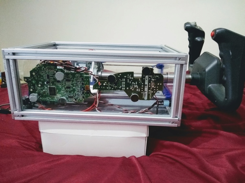
Thanks for the design Jay. I tried it out with DCS and it works A+++
I used 20 mm x 20 mm T-Slot Aluminum and 6mm plexiglass for the case.
I have push on push off lit switch which enables the motors using the white and gray wires from the photo diode board and a 1K resistor for current limiting. The LED pins on the board lights the switch.
I did the 1ohm resistor mod and it is well worth it. The power on the yoke is very strong.
It was easy to adapt the CH flight yoke to the 25mm tube.
I am going to enable the switches on the yoke by using the CH electronic USB board inside the yoke housing.
Then run a single usb cable out the back.
- tomzah
- Posts : 18
Join date : 2018-12-05
Re: Finished and it works great
Sat Jan 19, 2019 10:06 pm
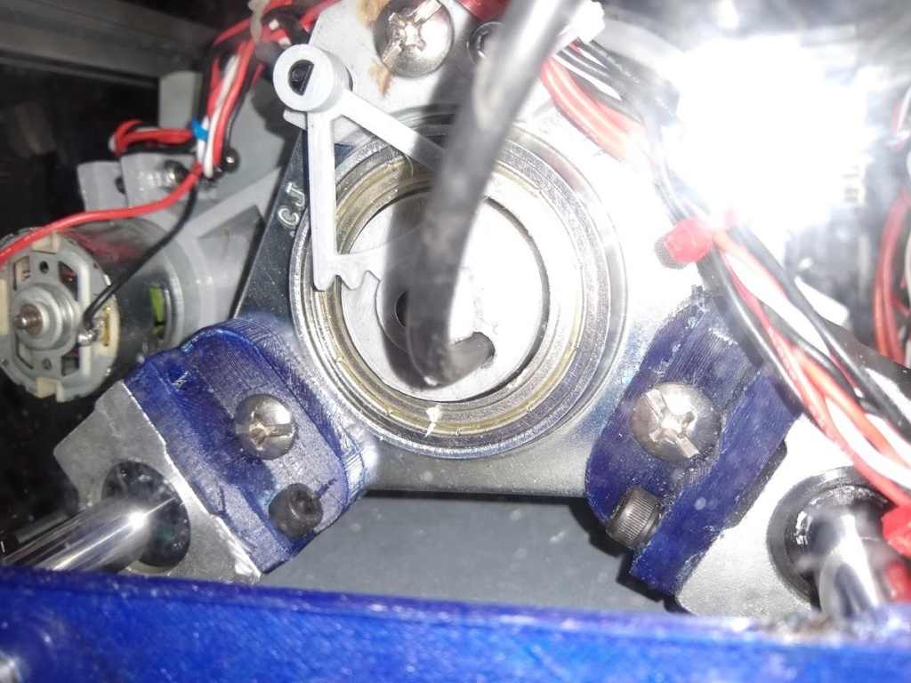
I added the CH's Yoke USB board to the yoke and ran the cable out the back.
I drilled a hole just big enough to pass the cable through the back plastic gear mount.
Now I have all the stock yoke switches working.
It was simpler to just run 2 usb cables out the back and attach them to a hub .
I drilled a hole just big enough to pass the cable through the back plastic gear mount.
Now I have all the stock yoke switches working.
It was simpler to just run 2 usb cables out the back and attach them to a hub .
 AdminAdmin
- Posts : 114
Join date : 2017-08-31 
Re: Finished and it works great
Sun Jan 27, 2019 10:55 pm
Wow dude 
I am very impressed, you've done really nice job there. When I saw the pics I actually thought you've build v2 already
I like the idea of your LED switch so you get to see the power status through it. I might use that in v2 though;)
Did you get rid of the IR PCB completely? Looking at the MSFFB schematics, it shouldn't work with white and grey wire. Well, it obviously does, just seem strange to me.
Shame that DCS won't give us any "yoked" planes
Jay
- tomzah
- Posts : 18
Join date : 2018-12-05
Re: Finished and it works great
Mon Jan 28, 2019 12:27 am
Yes Jay you can eliminate the IR board entirely. I ran the white and gray wires to the front switch. I did add a 1K resistor in series to protect the circuit but I am not sure it is necessary. The white wires carry the encoded signal to ground and the gray wire is the emitter on the npn transistor so it is seeking ground.
Works like a champ... I ran the 2 led pins from the main board to the led on the switch.
Plastic Flex..
I used Pet-g . My printer seems to like it. I thought that the Pulley_HTD-3M-121T , if it had a 6 more teeth on it would really help slippage with the resistor mod..
On the pitch belt. .. I ordered the belt from Malaysia on E-Bay. The guy from the UK was killing me on shipping and the Asian belt guy was cheap.
However the asian belt did not work well because it was too thick/stiff for the tight turns around the pulley s.
It took a while but i thinned the belt a bunch. Almost to the kevlar. It works great now.
So a lesson learned.. Belt thickness matters.
My DCS , using the P51 trainer, supported the FFB2 without a problem.
Once I got the belt tension correct (its a bit touchy) version V1 is a real winner in my book. (a belt tensioner scheme on the pitch belt would be a good idea).
Like I mentioned In a fatal dive with the P51 there was enough holding power to cause some flexing in the plastic yoke and a bit of creaking sounds between the 2 plastic shells of the yoke. (I was impressed!)
Flying a normal Cessna that kind of force would never be needed but in a combat plane it happens a lot.
Set up properly the V1 does a great job.
Thanks again for your work..
https://www.ebay.com/itm/BSFn-16mm-Green-On-Off-LED-12V-Latching-Push-Button-Power-Switch-Waterproof-/322294055776?hash=item4b0a390360
- AdminAdmin
- Posts : 114
Join date : 2017-08-31
Re: Finished and it works great
Wed Feb 20, 2019 9:12 pm
tomzah wrote: if it had a 6 more teeth on it would really help slippage with the resistor mod..
Just a quick reply,
There's a small hole "under" those teeth where you suppose to strap a zip tie around the belt. Once you do that, the belt can't slip;)
Sorry for the lack of instructions guys, still busy though.
Jay
- tomzah
- Posts : 18
Join date : 2018-12-05
Re: Finished and it works great
Sun Mar 03, 2019 7:48 pm
lol.. I see that now..
That will indeed fix it!
That will indeed fix it!
 Strale
- Posts : 26
Join date : 2018-10-09
Re: Finished and it works great
Sun Mar 10, 2019 11:32 pm
Tomszah
Could you please explain - in a simple and stupid proof way - how to get rid of the IR PCB ??
would be interested in.
Thanks
Could you please explain - in a simple and stupid proof way - how to get rid of the IR PCB ??
would be interested in.
Thanks
- tomzah
- Posts : 18
Join date : 2018-12-05
Re: Finished and it works great
Mon Mar 11, 2019 12:31 am
If you do not need to turn the motors off while playing on the PC simply cut the wires off the connector.
Same with the throttle pot.
In reality there is little need to be able to switch off the motors.
Many software titles will shut the motors off for you.
DCS for one..
Turning off your pc does this also.
Pulling the usb connector shuts it off.
Pulling the AC power plug does this too.
If there is a need to switch the motors off you need to connect the white and the gray wires together.
I would recommend a resistor to connect the 2 wires together verses just twisting the 2 wires together.
A 1000 ohm sometimes called 1k ohm is a good value. The resistor greatly limits any voltage flowing between the 2 wires.
But again this may not be a problem and tying the 2 wires together may be ok. I happen to have several thousand resistors laying around in my junk box.
And again if you have no need to turn off the motors than just cut the wires off
- Strale
- Posts : 26
Join date : 2018-10-09
Re: Finished and it works great
Mon Mar 11, 2019 8:36 am
Hi Tomzah,
thanks a lot for the easy instruction !
as i have a power switch (like Jay's layout) i think that cutting off the power through the switch will do the trick
So checking in my electronics bag the value of the resistors i still have and then will short the grey and white adding the resistor.
Of course still to figure out why i don't have any" "motor activity" when usb and power plugged in ! (please check my post "Need Support")
Thanks
Permissions in this forum:
You cannot reply to topics in this forum|
|
|