
 desktop_pilot
- Posts : 16
Join date : 2019-06-18
Location : The land of 10,000 lakes
 Modified V2 Yoke Build
Fri Jul 05, 2019 3:14 pm
Hello everyone,
I wanted to start a thread related to my build of a V2 yoke but modified to fit my sim. I want to provide everyone interested in the V2 concept with some additional information so that anyone looking to build or incorporate parts or ideas from the V2 will have some place to start.
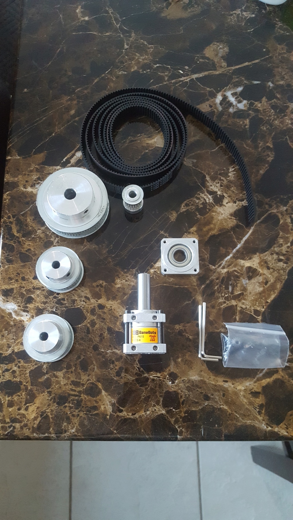
My build has the following parts:
Banebots P61 gearbox (for the RS-500 motors) in a 4:1 ratio
The belt is 3mm pitch x 15mm width
The pulleys for the roll axis are 20 teeth on the smaller one and 72 teeth on the larger one
The pulleys for the pitch axis are 40 teeth
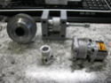
I have now received all of the above listed parts and am going to incorporate them into the current yoke in my sim which is built off a BFF Simulation design. My current yoke uses bungee cords to provide the resistance to the control movement but that of course means the yoke always returns to center. The reason I used the design from BFF simulation is because I was planning to add his control loading system later on. The cost of the control loading parts are the only reason I am changing my design and going this route as the four digit figure is a little hard on my pocket book. I am currently in the process of designing and constructing the new carrier plate to which all of the linear bearings and hardware for the roll axis will attach. I have included some pictures of the parts I have listed above as well as a couple showing my intended build.
I will be providing updates as I progress in my endeavor, wish me luck!


I wanted to start a thread related to my build of a V2 yoke but modified to fit my sim. I want to provide everyone interested in the V2 concept with some additional information so that anyone looking to build or incorporate parts or ideas from the V2 will have some place to start.
My build has the following parts:
Banebots P61 gearbox (for the RS-500 motors) in a 4:1 ratio
The belt is 3mm pitch x 15mm width
The pulleys for the roll axis are 20 teeth on the smaller one and 72 teeth on the larger one
The pulleys for the pitch axis are 40 teeth
I have now received all of the above listed parts and am going to incorporate them into the current yoke in my sim which is built off a BFF Simulation design. My current yoke uses bungee cords to provide the resistance to the control movement but that of course means the yoke always returns to center. The reason I used the design from BFF simulation is because I was planning to add his control loading system later on. The cost of the control loading parts are the only reason I am changing my design and going this route as the four digit figure is a little hard on my pocket book. I am currently in the process of designing and constructing the new carrier plate to which all of the linear bearings and hardware for the roll axis will attach. I have included some pictures of the parts I have listed above as well as a couple showing my intended build.
I will be providing updates as I progress in my endeavor, wish me luck!
augustopaulo likes this post
- flyallthings
- Posts : 7
Join date : 2019-06-03
Re: Modified V2 Yoke Build
Fri Jul 05, 2019 8:37 pm
Best of luck! Where did you buy your pulleys from?
- desktop_pilot
- Posts : 16
Join date : 2019-06-18
Location : The land of 10,000 lakes
Re: Modified V2 Yoke Build
Fri Jul 05, 2019 9:34 pm
The belt and pulleys all came from Amazon, I ordered from several different sellers as no single seller had everything I was looking for so best to just search around. Even though they came from different sellers the parts seem very similar and I'm guessing that they probably come from just a few Chinese factory's. The gearboxes came direct from Banebots.
- desktop_pilot
- Posts : 16
Join date : 2019-06-18
Location : The land of 10,000 lakes
Re: Modified V2 Yoke Build
Tue Jul 09, 2019 6:40 pm
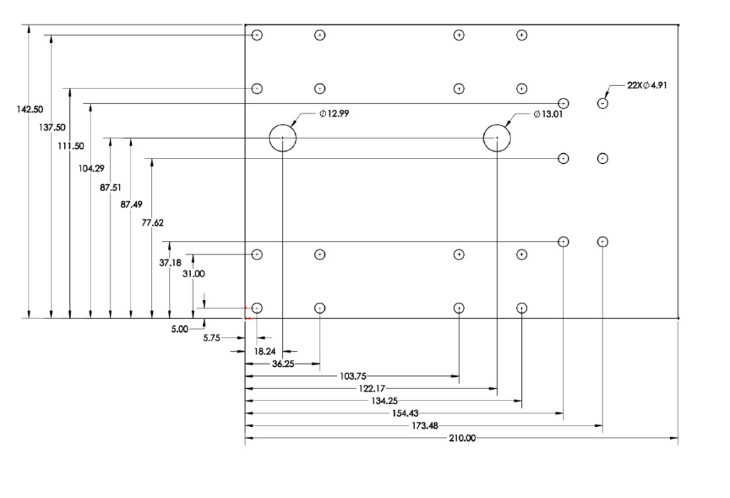
I now have all of the holes drilled in the carrier plate, I tried mounting the bearings and gearbox and the dimensions seem to work alright. There are a couple bearings that seem to tighten on the shaft after I snug up their mounting screw, I think that is due to the cheap Chinese manufacturing on those. I will have to buy a good tap and chase those threads. I also have not been a fan of the loud noise of the balls recirculating inside those bearings so I think I may try to 3D print some bushings.
Pics so far:

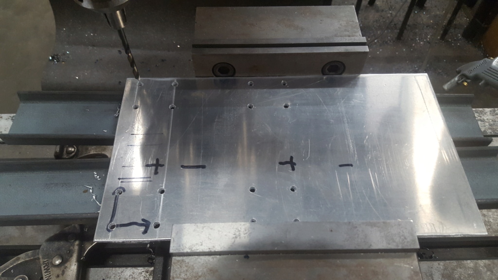

The DRO really made the positioning easy.


Pics so far:
The DRO really made the positioning easy.
- flyallthings
- Posts : 7
Join date : 2019-06-03
Re: Modified V2 Yoke Build
Wed Jul 10, 2019 7:32 am
Looking great! What motors are you using?
I've been researching motors all evening. From what I can see, the motors I choose should not ever be allowed to reach their stall current. So I'm guessing I have to current limit them. So if a motor has a stall current of 20A, and I use a 5A power supply, is that good enough for current limiting? Sorry for the questions, I'm really not the smartest when it comes to electronics.
I've been researching motors all evening. From what I can see, the motors I choose should not ever be allowed to reach their stall current. So I'm guessing I have to current limit them. So if a motor has a stall current of 20A, and I use a 5A power supply, is that good enough for current limiting? Sorry for the questions, I'm really not the smartest when it comes to electronics.
- desktop_pilot
- Posts : 16
Join date : 2019-06-18
Location : The land of 10,000 lakes
Re: Modified V2 Yoke Build
Wed Jul 10, 2019 4:18 pm
I plan to use the stock motors from the Sidewinder joystick, that is the reason for the gearboxes. It gives me more torque without having to mess with finding different motors. Not sure if the torque from this gear ratio is going to be what I am looking for yet but it is a place to start, I can also play with the pulley sizes if the force is not correct.
As to your question, what are some of the motors and power supplies you are looking at? As the load on the motor increases the current through the windings will go up and obviously motors don't like being hot. Same can be said for the power supplies, it's not really good for them to be operating at high output for long amounts of time. In mine I am ditching the stock power supply in favor of a higher current 24v Meanwell unit. This way even if I want to increase the power to the motors the supply will be able to handle it. What circuit are you looking at to control the motors? I chose to use the Sidewinder board as the motor control circuit is very well designed with feedback based off current sense resistors.
As to your question, what are some of the motors and power supplies you are looking at? As the load on the motor increases the current through the windings will go up and obviously motors don't like being hot. Same can be said for the power supplies, it's not really good for them to be operating at high output for long amounts of time. In mine I am ditching the stock power supply in favor of a higher current 24v Meanwell unit. This way even if I want to increase the power to the motors the supply will be able to handle it. What circuit are you looking at to control the motors? I chose to use the Sidewinder board as the motor control circuit is very well designed with feedback based off current sense resistors.
- flyallthings
- Posts : 7
Join date : 2019-06-03
Re: Modified V2 Yoke Build
Thu Jul 11, 2019 10:40 pm
I'm looking at springing for an ODrive board. It's a bit pricey but it can handle large motors and seems to have some good bells and whistles built right in. The motors are 32V and have a stall current of 65A. Obviously I don't want to run them that high as they would blow breakers and probably start the house on fire. But am I able to use less power on the motors and make up for the torque using gear boxes and pulleys?
Like, could I use a 24V 20A power supply for a motor like that? Sorry for the dumb questions.
Like, could I use a 24V 20A power supply for a motor like that? Sorry for the dumb questions.
- desktop_pilot
- Posts : 16
Join date : 2019-06-18
Location : The land of 10,000 lakes
Re: Modified V2 Yoke Build
Fri Jul 12, 2019 2:16 pm
flyallthings wrote:Like, could I use a 24V 20A power supply for a motor like that?
"Short answer, "yes" with an "if." Long answer, "no" with a "but."", OK Simpsons quote aside, it would help to have a little more information about the motor. By maximum stall current I am assuming you are referring to the current draw at nominal voltage when the motor is stalled. That obviously is not ideal and will generate a tremendous amount of heat in the windings. There should, however, be a separate maximum current where the motor can operate in the stalled state with no damage to the wingings, it will of course be much lower than the 65 amps you have listed. The lower voltage provided by the above power supply would be beneficial to operating in the stalled state as that will lead to a lower current going through the motor. As you stated, a reduction system would help to decrease the torque required from the motor and thus the current since in a DC motor the torque and current are directly related.
I am not familiar with the Odrive motor controller, the reason that I chose to go with the Sidewinder joystick is that it can be hooked up to the computer as a Human Interface Device (HID). From my cursory look at the specs it seems that the Odrive is more designed for automation. I am not sure how it would connect to the flight simulator and how the force feedback information would be sent to and interpreted by that system. I am guessing there would need to be some type of intermediary system to do that. I know there have been a few groups that have been working on an open source force feed back system specifically geared towards helicopter cyclics. I believe they were last working on a way to utilize an arduino to connect to the computer as a HID and use some type of motor shield to control the motors. If you have not come across the forums related to their work I would recommend checking out the forum below:
https://forums.eagle.ru/showthread.php?t=172964
- Robertw
- Posts : 10
Join date : 2018-10-12
Re: Modified V2 Yoke Build
Mon Aug 03, 2020 1:49 pm
Any updates on this build?
- desktop_pilot
- Posts : 16
Join date : 2019-06-18
Location : The land of 10,000 lakes
Re: Modified V2 Yoke Build
Wed Aug 05, 2020 7:43 pm
Believe it or not I was just about to post a progress update.
Due to other life obligations and some amount of procrastination on my part I needed to put this project on the back burner. I now have some time to get back to work on this so stay tuned, current progress is detailed below.
Right now I have the yoke mounted in the sim but am using some bungee cords to provide resistance to movement. I needed to temporarily set it up this way so that I would have a yoke to use for the SimVenture 2020 fly-in. It was a three day mad rush to get brackets printed and stuff hooked up so that I could use it in some fashion.

I do have the yoke wired with two push buttons for PTT and AP disconnect as well as a trim and hat switch.

I designed the trim switch to mimic a S-Tec / Cygnet unit, the design is on Thingiverse for anyone interested in printing one:
Elevator trim switch - https://www.thingiverse.com/thing:4560646

I also spent some time at my lathe boring the pulleys I purchased so that they will fit on the banebots gearboxes' shafts. The large pulley also had to be bored to fit my yoke shaft. I designed and printed a simple bracket for the idler pulley for the pitch axis. It still needs a proper shaft but the carriage bolt should work in the meantime.
Right now I am working on designing a yoke bushing since the yoke shaft is only supported by a single pillow block right now. I am also working on the electronics for a motorized trim wheel so that the trim switch will control a stepper motor that turns the wheel. That is then hooked to a rotary encoder and using an Arduino will send the signals to the joystick board as though I am pressing the trim switches. This way I can use either the trim switch on the yoke or manually move the trim wheel if I so chose.
Due to being slow at work right now I am on temporary leave and trying to get as much done this month as possible!
Updates to come as I continue to make progress on this.
Due to other life obligations and some amount of procrastination on my part I needed to put this project on the back burner. I now have some time to get back to work on this so stay tuned, current progress is detailed below.
Right now I have the yoke mounted in the sim but am using some bungee cords to provide resistance to movement. I needed to temporarily set it up this way so that I would have a yoke to use for the SimVenture 2020 fly-in. It was a three day mad rush to get brackets printed and stuff hooked up so that I could use it in some fashion.
I do have the yoke wired with two push buttons for PTT and AP disconnect as well as a trim and hat switch.
I designed the trim switch to mimic a S-Tec / Cygnet unit, the design is on Thingiverse for anyone interested in printing one:
Elevator trim switch - https://www.thingiverse.com/thing:4560646
I also spent some time at my lathe boring the pulleys I purchased so that they will fit on the banebots gearboxes' shafts. The large pulley also had to be bored to fit my yoke shaft. I designed and printed a simple bracket for the idler pulley for the pitch axis. It still needs a proper shaft but the carriage bolt should work in the meantime.
Right now I am working on designing a yoke bushing since the yoke shaft is only supported by a single pillow block right now. I am also working on the electronics for a motorized trim wheel so that the trim switch will control a stepper motor that turns the wheel. That is then hooked to a rotary encoder and using an Arduino will send the signals to the joystick board as though I am pressing the trim switches. This way I can use either the trim switch on the yoke or manually move the trim wheel if I so chose.
Due to being slow at work right now I am on temporary leave and trying to get as much done this month as possible!
Updates to come as I continue to make progress on this.
Robertw likes this post
- Robertw
- Posts : 10
Join date : 2018-10-12
Re: Modified V2 Yoke Build
Fri Aug 21, 2020 3:04 pm
Looking Good! I have started building V1 of the FFB yoke. I have time on my hands as well due to slow downs at work. I will be following your progress.
- desktop_pilot
- Posts : 16
Join date : 2019-06-18
Location : The land of 10,000 lakes
Re: Modified V2 Yoke Build
Sun Aug 23, 2020 4:36 am
Robertw: Have you measured the voltage and current draw of the motors? If you have could you let me know what they are, the reason for this question is evident below. 
Quick update here:
I have all the hardware and electronics setup and "working". I say that as the roll axis has decent force when I am flying in a C172 and fully deflect the ailerons left or right and it has a really nice return to center. The pitch axis on the other hand is definitely in need of some work. I am using 3D printed PLA bushings in the bearing blocks and they apparently have too much friction. When I am sitting on the ramp the yoke does not move forward from the weight of the elevator nor does it return if I deflect it during flight. My multi-meter shows that power is being applied to the motor and I can feel there is a force I am pushing against but it is not strong enough. I have not checked the current to the motor yet so I am not sure where the trouble is although I am sure my bushings are not helping. I am going to try modifying the PLA bushings first and if that doesn't work I will have to look for a different bearing setup, maybe the bearing/wheel and aluminum extrusion idea is the way to go.
- Robertw
- Posts : 10
Join date : 2018-10-12
Re: Modified V2 Yoke Build
Sun Aug 23, 2020 2:50 pm
I haven't measured the current or voltage to the motors. So far I am still printing parts and waiting for some belts to show up. I haven't even disassembled my sidewinder yet. I am still machining the bearing holders for the yoke shaft. I found the mounted bearings online in the US ( no source in Canada) shipping was over a $100 so rather than spending on shipping I grabbed some scrap aluminum and got to work. I can measure the current and voltage in the assembled unit if its not too hard to get to the leads.
- Robertw
- Posts : 10
Join date : 2018-10-12
Re: Modified V2 Yoke Build
Sun Aug 23, 2020 9:34 pm
I just measured the voltage and current in windows 10 control panel using the configuration panel. Both motors measured 6 volts at full deflection and 0.7 amps current. I suspect the pla bushing are causing too much friction as well. If you don't want to use a linear bearing try PTFE it has low friction and is easily machined.
- desktop_pilot
- Posts : 16
Join date : 2019-06-18
Location : The land of 10,000 lakes
Re: Modified V2 Yoke Build
Sun Aug 23, 2020 9:50 pm
I just measured the current and voltage to my motors as well, max current is about 0.7 amps. Voltage sent to the motors ranged from 9v to 16v with about 12v while sitting in the neutral position. Maximum voltage drop across the motors is about 6v as well. Nice to see that our readings are corresponding very well.


I measured the current first and in my haste to measure the voltage drop across the motor forgot to swap the meter over to voltage measurement and thus had a direct short. Unfortunately I heard a pop and let the magic smoke out from somewhere on the board. After taking a look I think I spotted a crack on one of the MOSFETs. It is one of the two controlling the pitch axis which makes sense as that is what I was measuring at the time. When I measure across the motor connector pins now I get about 3.1M ohms meaning there is a short in one of the MOSFETs in that circuit.

Before I saw your post I was not sure what to expect for current to the motors but remembered that I had previously found a website where someone was modifying one of these joysticks to power much larger motors.
simprojects.nl/ms_siderwinder_ff2_hack
After taking a look at their site again I see that the expected current flow is indeed about 0.7 amps. After looking at the joystick's gearing again I realized that the reduction ratio is actually much larger than what I have, rough counting and guesstimating puts it at about 33:1!
My calculated ratio for my pitch axis is only 5:1 and roll 14:1. If I change my pulley size for pitch I can double that to 10:1 but I am still coming up very short. I think I need to change my gearboxes as well. I was also thinking of modifying the current sense resistors on the board to double the current to the motors but was concerned about the stock MOSFETs as the previously mentioned person changed theirs. But, since I need to replace one now I guess I might as well change them all. c'est la vie
I measured the current first and in my haste to measure the voltage drop across the motor forgot to swap the meter over to voltage measurement and thus had a direct short. Unfortunately I heard a pop and let the magic smoke out from somewhere on the board. After taking a look I think I spotted a crack on one of the MOSFETs. It is one of the two controlling the pitch axis which makes sense as that is what I was measuring at the time. When I measure across the motor connector pins now I get about 3.1M ohms meaning there is a short in one of the MOSFETs in that circuit.
Before I saw your post I was not sure what to expect for current to the motors but remembered that I had previously found a website where someone was modifying one of these joysticks to power much larger motors.
simprojects.nl/ms_siderwinder_ff2_hack
After taking a look at their site again I see that the expected current flow is indeed about 0.7 amps. After looking at the joystick's gearing again I realized that the reduction ratio is actually much larger than what I have, rough counting and guesstimating puts it at about 33:1!
My calculated ratio for my pitch axis is only 5:1 and roll 14:1. If I change my pulley size for pitch I can double that to 10:1 but I am still coming up very short. I think I need to change my gearboxes as well. I was also thinking of modifying the current sense resistors on the board to double the current to the motors but was concerned about the stock MOSFETs as the previously mentioned person changed theirs. But, since I need to replace one now I guess I might as well change them all. c'est la vie
- Robertw
- Posts : 10
Join date : 2018-10-12
Re: Modified V2 Yoke Build
Sun Aug 23, 2020 11:27 pm
Sounds like a bit of serendipity on popping the mosfets. That sidewinder hack looks good. And yes it looks like a gearbox change is in order. Bigger motors, higher gear ratio, more power!
- desktop_pilot
- Posts : 16
Join date : 2019-06-18
Location : The land of 10,000 lakes
Re: Modified V2 Yoke Build
Tue Sep 01, 2020 4:28 am
I completed my work on the board by swapping out the MOSFETs and also stacked one extra one ohm resistor on each of the current sense resistors to cut the resistance in half. The increased current to the motors really made the roll axis much more realistic. I am very happy with the feel of the roll axis now although I wish I had chosen a higher gear ratio so that I would not be pushing so much current through the motor at 100% in FS Force.


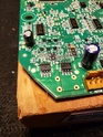
My issue with the pitch axis is continuing though, when I first tried it after the modifications everything worked fine when I pulled the yoke towards me. My oscilloscope showed a 30 Khz square wave with a duty cycle of between 50 and 100 percent depending on the yoke's position. When I pushed the yoke forward past the center position there was a high pitched noise coming from the motor and the scope showed rapidly fluctuating noise in the signal. After only a little while the underlying square wave went to 100% and stayed there no matter what the yoke postition. The power supply now has a clicking noise that repeats about every second. I took a look at the board and found a dual BJT IC that looks like it has a crack in it.
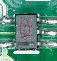
When I measure the resistance it is drastically different than the other ICs of that same type. I am not sure if the original MOSFET blowing caused damage to this BJT that now failed due to me using and testing the board or if this is new from some other problem. I have ordered up some breakout boards from Amazon so I can take some of these ICs off the board and test them. I will post an update when I have gotten some results from my testing.
My issue with the pitch axis is continuing though, when I first tried it after the modifications everything worked fine when I pulled the yoke towards me. My oscilloscope showed a 30 Khz square wave with a duty cycle of between 50 and 100 percent depending on the yoke's position. When I pushed the yoke forward past the center position there was a high pitched noise coming from the motor and the scope showed rapidly fluctuating noise in the signal. After only a little while the underlying square wave went to 100% and stayed there no matter what the yoke postition. The power supply now has a clicking noise that repeats about every second. I took a look at the board and found a dual BJT IC that looks like it has a crack in it.
When I measure the resistance it is drastically different than the other ICs of that same type. I am not sure if the original MOSFET blowing caused damage to this BJT that now failed due to me using and testing the board or if this is new from some other problem. I have ordered up some breakout boards from Amazon so I can take some of these ICs off the board and test them. I will post an update when I have gotten some results from my testing.
- Robertw
- Posts : 10
Join date : 2018-10-12
Re: Modified V2 Yoke Build
Tue Sep 01, 2020 1:40 pm
Did you add the diodes to the mosfets as shown in the mod? It could have been weakened by the first blow out.
- desktop_pilot
- Posts : 16
Join date : 2019-06-18
Location : The land of 10,000 lakes
Re: Modified V2 Yoke Build
Wed Sep 02, 2020 12:10 am
Since the Schottky diodes are there to lessen the heat that the MOSFETs have to dissipate they would not have had any effect on what the dual BJT was experiencing. I did not add the diodes since I went with better MOSFETs and am only running twice the current. I figured I should be able to mitigate that additional heat with some small heatsinks that I have for stepper driver ICs if needed.
- Marek33
- Posts : 6
Join date : 2019-02-14
Re: Modified V2 Yoke Build
Thu Sep 17, 2020 2:29 pm
Schottky diodes must have. It's a overvoltage protection (inductive load).
Mark
Mark
- desktop_pilot
- Posts : 16
Join date : 2019-06-18
Location : The land of 10,000 lakes
Re: Modified V2 Yoke Build
Fri Sep 18, 2020 4:34 am
If the circuit was using BJTs then Schottky diodes would absolutely be required but MOSFETs have built in body diodes that can be used instead. The purpose of the external Schottky diodes used in parallel with MOSFETs is to have them pass current rather than the MOSFET body diodes thus reducing the current through the MOSFET package. I elected to mitigate the heat from the MOSFET package with heatsinks if needed.
- desktop_pilot
- Posts : 16
Join date : 2019-06-18
Location : The land of 10,000 lakes
Re: Modified V2 Yoke Build
Tue Dec 01, 2020 4:58 am
Sorry for the lack of updates on the project. I got a new job and it plus some other obligations have been taking up all my free time. After more research and testing I have come to the realization that I am at the limit of my knowledge. I have thus decided to purchase another FFB 2 stick to use for this build. My plan is to put it into my setup without all the upgrades and see what it can do. If I am not satisfied with the performance I can then look to modify it. This will also give me the opportunity to compare this second board to the damaged one in the hope to gain more understanding of what may be wrong with the damaged board.
Permissions in this forum:
You cannot reply to topics in this forum|
|
|